


GGD low voltage switchgear assembly
Category:
Low voltage switchgear set
Phone:
Product Detail
Overview
GGD low-voltage complete switchgear (AC low-voltage power distribution cabinet) (hereinafter referred to as the device) is suitable for power distribution of AC 50Hz, rated working voltage 400V, and rated working current up to 3200A for power users in power plants, substations, and factories and mines. In the system, it is used for power conversion, distribution and control of power, lighting and power distribution equipment.
The device meets the requirements of GB7251.1-2005 "Low-voltage complete switchgear and control equipment Part I: type production, test and partial type test complete sets of equipment" and JB/T5877-2002 "Low-voltage fixed closed switchgear complete sets".
The device has the characteristics of high breaking capacity, flexible electrical scheme, convenient combination, series, strong practicability, novel structure and high protection level.
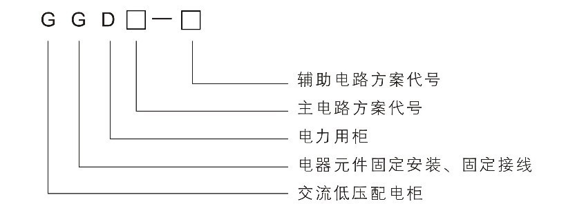
Product model and its meaning
Use environmental conditions
For indoor installation.
The ambient air temperature is not higher than +40°C, not lower than -5°C, and the average temperature within 24 hours is not higher than +35°C.
The air is clean, and the relative humidity does not exceed 50% when the maximum temperature is 40°C. Higher relative temperatures are allowed at lower temperatures. For example: the relative humidity is 90% at +20°C, but it should be considered that moderate condensation may occur occasionally due to temperature changes.
The altitude does not exceed 200m.
Pollution level 3.
The inclination of the device installation to the vertical plane does not exceed 5 degrees.
The transportation and storage temperature is -25℃~+55℃, and it can reach +70℃ in a short period of time (not exceeding 24h).
When users have special requirements, they can negotiate with the manufacturer.
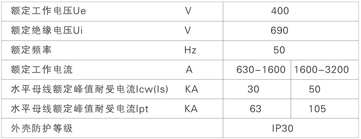
Basic electrical parameters
Structural Features
The basic structure of the device is a combined structure, with KS profile (basic modulus E=20mm) as the main structural component, and it is fastened with self-tapping locking screws and 8.8-grade high-strength bolts. The frame parts and special supporting parts are supplied by the designated steel production plant to ensure the accuracy and quality of the cabinet. The components of the device are designed according to the principle of modules, and there are 20mm module mounting holes. The general coefficient is high, which can not only shorten the production cycle of the factory, but also improve the work efficiency.
Fully considering the heat dissipation problem during the operation of the cabinet body, there are different numbers of heat dissipation holes and slots at the upper and lower ends of the cabinet body. When the electrical components of the cabinet are heated, the heat rises and is discharged through the upper slot, while the cold air is continuously replenished into the cabinet through the lower slot, so that the sealed cabinet forms a natural ventilation channel from bottom to top to achieve heat dissipation and cooling.
The cabinet door is connected to the frame with a rotating shaft type living hinge, which is easy to install and disassemble. There is a "mountain" type rubber strip embedded in the hem of the door. When the door is closed, it has a certain compression stroke with the strip between the door and the cabinet frame, which can prevent the door from directly colliding with the cabinet body, and also improves the door and cabinet frame. degree of protection.
The top cover of the cabinet can be removed when necessary, which is convenient for the assembly and adjustment of the main busbar on site.
Designed a special ZNJ type combined bus clamp. The busbar clamp is made of high-strength, high flame-retardant alloy material thermoplastically formed, with high insulation strength, good self-extinguishing performance, and unique structure. It can be conveniently combined with single busbar clamp or double busbar clamp just by adjusting the building block.
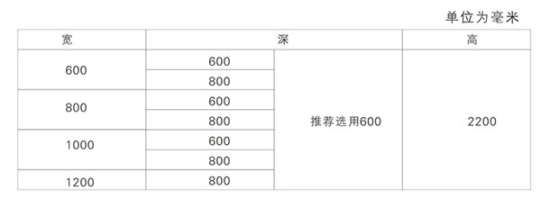
See the table below for the dimensions of the device
Complete set of products
A. Packing list;
B. Product instruction manual;
C. Product certificate;
D. Factory test report;
E. Relevant electrical drawings;
F. List of spare parts and special tools to be provided;
G. The information required by the contract may be provided.
Users need to provide information
A. Main circuit scheme diagram or single-line system diagram;
B. Auxiliary circuit schematic diagram or wiring diagram;
C. List of components in the cabinet;
D. Arrangement diagram and layout diagram of power distribution room;
E. Other special requirements inconsistent with the normal use of the product;
F. Cabinet color.
Installation and use
After the device arrives at the receiving location, first check whether the packaging is complete and undamaged. If any problem is found, the relevant department should be notified to find out the reason. For the product that is not installed immediately, it should be placed in an appropriate place according to the normal use conditions.
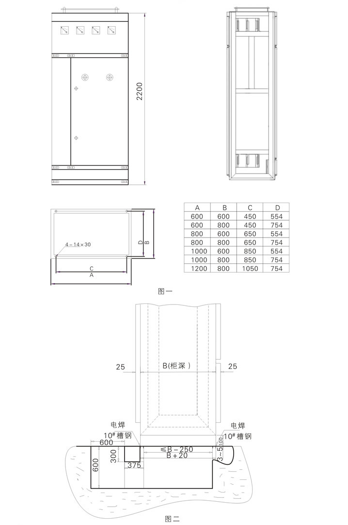
The installation of the device should be carried out according to Figure 1 and Figure 2, and the basic channel steel and bolts (M12) should be prepared by the user.
After the device is installed, the following items need to be inspected and tested before it is put into operation; manual operation of various switches should be flexible and free of abnormalities
Various jamming phenomena;
A. Whether the electrical equipment and control wiring installed in the device meet the requirements of the factory's drawings;
B. Check whether the insulation resistance of the main circuit and the control circuit meets the specified requirements:
C. Check whether the installed electrical equipment is in good contact and meets its own technical requirements;
D. Check whether the action of mechanical interlock mechanism and electrical interlock device is correct and reliable, and should meet the system requirements;
E. Check whether there is any foreign matter inside the device and whether the mounting screws of the parts are loose.
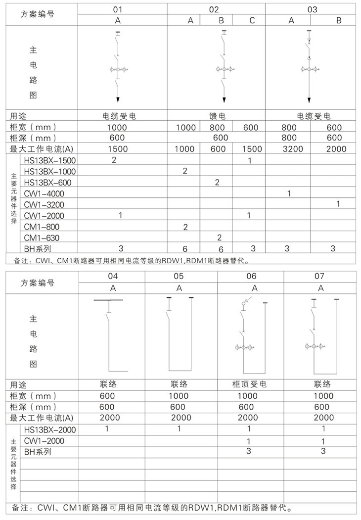
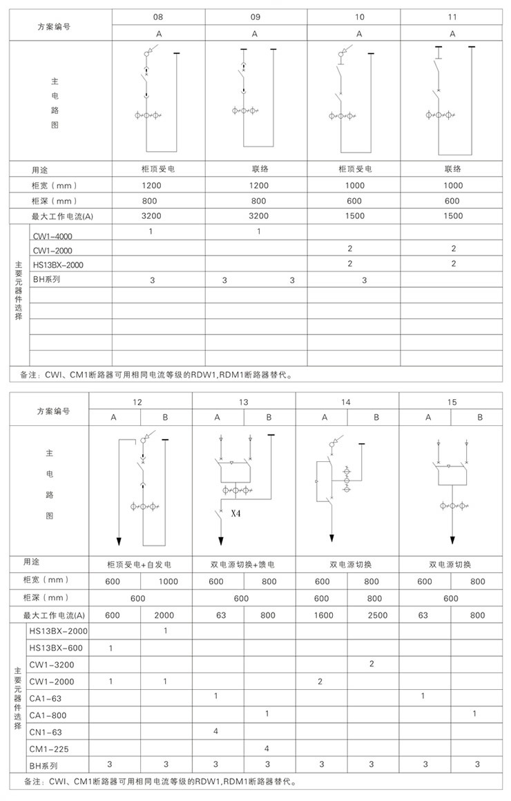
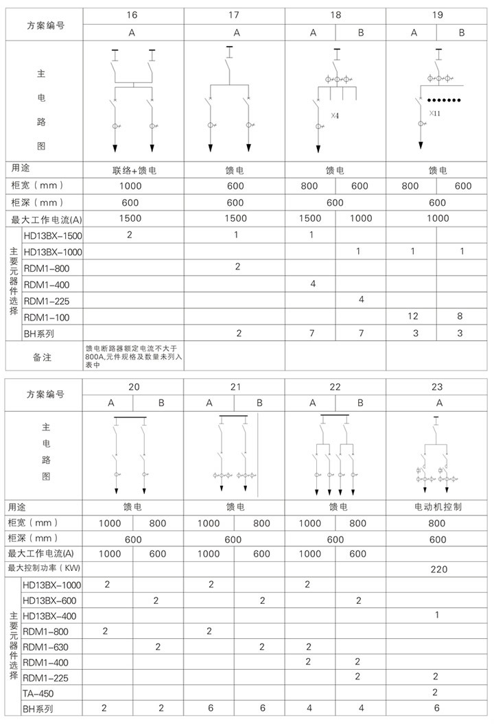
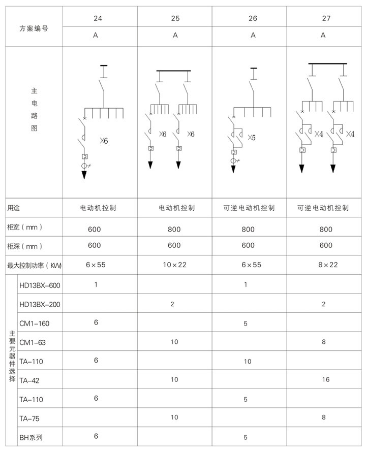
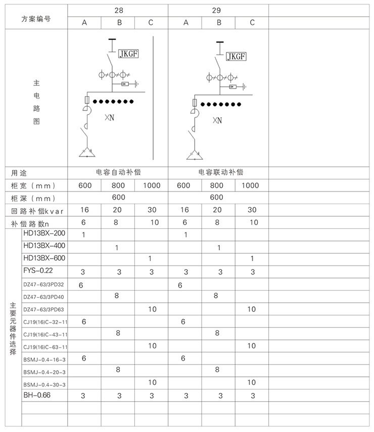
Main Circuit Diagram
Keywords: high voltage | low ark | box complete sets of equipment
Recommended product


 low pressure enclosed power cabinet")
Online message
E-mail:sales@hfliyuan.com
Tel:86-0551-62578999
Add: Liyuan High-tech Industrial Park, intersection of Tangkou Road and Bagongshan Road, Taohua Industrial Park, Jingkai District, Hefei City

Follow us