


KYN28A-12 is equipped with removable metal enclosed switchgear
Category:
Medium voltage switchgear set
Phone:
Product Detail
Overview
KYN28A-1 2 armored removable metal-enclosed switchgear (referred to as switchgear) is a new product designed and developed by Hefei Liyuan Power Equipment Co., Ltd. on the basis of foreign advanced design and manufacturing technology, which can replace various old The type of armored metal-enclosed switchgear has the following obvious advantages: the shell of the product is completely made of aluminum-zinc plate processed by CNC machine and assembled with bolts, which has high mechanical strength and effectively guarantees The neatness and beauty of the product. The cabinet door is coated with plastic spraying, which has strong anti-shock and corrosion resistance. The product shell has a protection level of Confucianism 4X.
The main switch of this product can be equipped with 3AH of MENS company, VD4 vacuum circuit breaker of ABB company, C3 series fixed load switch, and also can be equipped with various domestic series vacuum circuit breakers (such as VSl, ZNl2) wait.
No matter what kind of circuit breaker is selected, its circuit breaker has the unique advantages of long life, high parameters, less maintenance and small size.
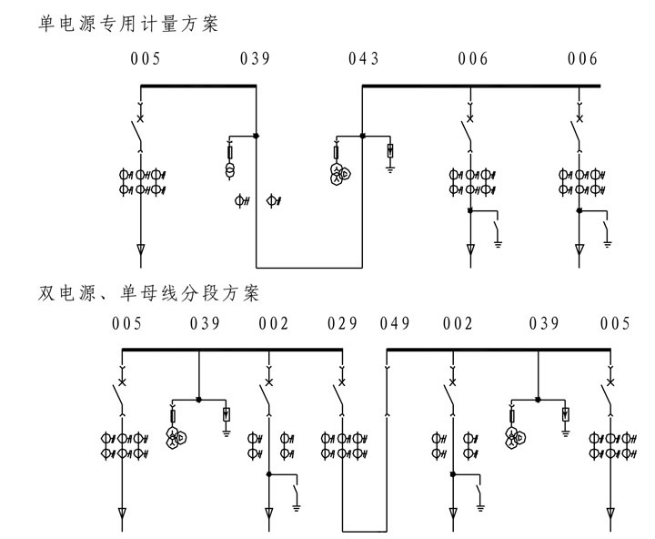
KYN28A-12 armored mid-mounted metal-enclosed switchgear is suitable for 3.6-12kV three-phase AC 50Hz power grid, used for receiving and distributing electric energy, and controlling, monitoring and protecting the circuit. It can be used in single-bus section system and double-bus section system. The switchgear meets the requirements of GB3906 "3-35kV AC metal-enclosed switchgear" and DL404 "Technical conditions for ordering indoor AC high-voltage switchgear" and other standards, and has perfect and reliable "five-proof" locking functions.
Model Description

Use environmental conditions
Normal use conditions:
Ambient temperature: the highest temperature is +40°C, the lowest temperature is -15°C, and the average temperature within 24 hours is not higher than +35°C.
Environmental humidity: The daily average relative humidity is 95% and below, and the monthly average relative humidity is 90% and below.
The maximum altitude does not exceed 1000m.
The earthquake intensity does not exceed 8 degrees.
No fire, no explosion hazard, no serious pollution, no chemical corrosive gas and severe vibration. Special Conditions of Use:
When the switchgear is installed in an area with an altitude greater than 1000mm, you must negotiate with the manufacturer to take necessary strong insulation measures when ordering.
When the maximum ambient temperature exceeds +40℃, the rated current-carrying capacity of the switchgear will be reduced by a certain coefficient, which must be confirmed by the manufacturer when ordering.
Special Notes:
The humidity in many areas of China is relatively high, and the temperature fluctuates quickly and in a large range. If the switchgear operates in this climate environment, there is a risk of condensation. Therefore, the user should It is guaranteed that the heater is turned on around the clock, but the heater may not be turned on when the switchgear with a load current above 1250A is in the running state.
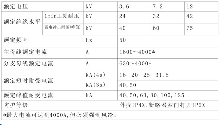
Main technical parameters of switchgear
Introduction to the main components of the primary circuit
The main electrical components of the primary circuit selected in the switchgear are for reference when selecting models. For more detailed instructions, please refer to the relevant product manuals.
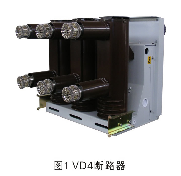
Vacuum circuit breaker is the most important electrical component in the primary circuit of switchgear. The main selections are VD4 vacuum circuit breaker produced by ABB company, 3AH vacuum circuit breaker produced by SIEMENS company, and VS1 vacuum circuit breaker produced by Senyuan company. Circuit breakers, etc., here only a brief description of the VD4 vacuum circuit breaker. VD4 vacuum circuit breaker VD4 vacuum circuit breaker is the most important electrical component in the primary circuit of the switchgear (see Figure 1). It is provided by ABB Group and fully meets the requirements of international standards and national standards.
VD4 vacuum circuit breaker can operate frequently and break short-circuit current multiple times within the working current range. The mechanical life can be as high as 30,000 times, and the number of short-circuit current breaking times at full capacity can be as high as 100 times. It is suitable for reclosing operation and has high operational reliability. Under normal working conditions, the circuit breaker is used within the range of allowable technical parameters to ensure safe and reliable operation. During use, the VD4 vacuum circuit breaker only needs a small amount of cleaning, lubrication and other maintenance work.
When the circuit breaker is used to control a 3.6-12kV motor, if the starting current is less than 600A and it is frequently started, it is recommended to install a zinc oxide arrester to limit the operating overvoltage. The specific requirements are determined by the user and the manufacturer when ordering. Negotiated to determine.
The operating mechanism matched with VD4 vacuum circuit breaker is a planar scroll spring operating mechanism with compact structure and stable performance. The operating mechanism simultaneously operates the three-phase interrupter. The scroll spring can be equipped with both manual and electric energy storage methods. The operating mechanism is suitable for automatic reclosing operation.
The basic configuration mode of the operating mechanism can meet the requirements of most users, and it has complete and reliable electrical and mechanical auxiliary components. VD4 vacuum circuit breaker handcart can be operated electrically.
For specific technical parameters, please refer to the relevant product manual.
Load switch
The main types of load switch are NAL12 type load switch and NALF12 type load switch-fuse combination appliance, FN12-12 D/630-20 type AC high voltage load switch, FN12-12(R)D/100-31.5 type AC high voltage load switch — fuse combination appliances, etc.
The load switch should have reasonable design, simple structure, convenient operation and stable performance. It is suitable for a wide range of medium voltage switchgear, and can be used for transformers, capacitors, cables, overhead lines, feeders and ring network systems.
The load switch can be operated when the door panel of the switch cabinet is closed, and the load switch and the grounding switch have reliable mechanical locking.
Under normal working conditions, the load switch can operate under rated parameters for a long time, requiring only a small amount of maintenance.
No gap zinc oxide arrester
The main types of arresters in the switchgear are the MWD gapless zinc oxide arrester produced by ABB and the domestic HY5WS arrester
Grounding Switch
The main types of earthing switch are EK6 type earthing switch produced by ABB company and JN15 type earthing switch made in China. The earthing switch has an auxiliary contact, which provides a signal of the opening and closing state of the earthing switch.
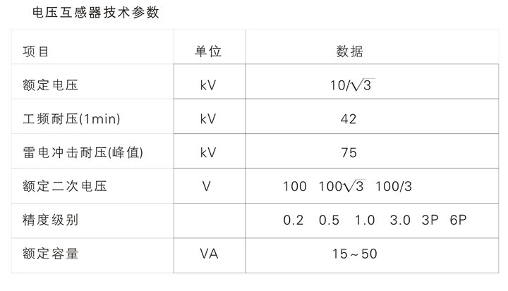
Current/Voltage Transformer
With the application and development of digital technology in measurement and protection, the requirements for measuring components in medium voltage systems have also changed. Compared with traditional measuring cells, today's measuring cells only need a small electrical signal to meet the requirements. The technical parameters of the current/voltage transformer are shown in the table below:

Introduction to the main components of the secondary circuit
Protection relay
User-specified protection relays can be configured according to user requirements.
Measuring instrument
The configuration of measuring instruments is mainly based on the requirements of users and meets the requirements of international standard measuring instruments guidelines. The company is mainly equipped with domestic advanced manufacturers' components, and can also be equipped with domestic instruments designated by users according to the requirements of users.
Other secondary components
The protection of the operating power supply of the switchgear adopts a miniature air switch, and a fuse can also be used.
The secondary terminal blocks of the switchgear all use Phoenix terminals.
The auxiliary switches and secondary plug-ins of the switch cabinet are all made of well-known company products with simple structure, excellent performance and reliable operation.
Switch cabinet structure
Overview
与此原文有关的更多信息要查看其他翻译信息,您必须输入相应原文 发送反馈 侧边栏 历史记录 已保存 提供建议The switch cabinet is composed of two parts: a fixed cabinet and a removable part (referred to as a handcart). According to the function of the electrical equipment in the cabinet, the cabinet body is divided into four different functional units with partitions. As shown in Figure 2, busbar room A, circuit breaker room B, cable room C, and low-voltage room D. The shell of the cabinet and the partitions between the functional units are made of aluminum-zinc-coated steel plates bent and then bolted.

The removable parts of the switchgear can be equipped with VD4, VS1, 3AH and other vacuum circuit breaker handcarts, current transformer handcarts, voltage transformer handcarts, isolation handcarts, etc.
A live display device (selected by the user) to detect the operation of the primary circuit can be installed in the switch cabinet. The device is composed of a high-voltage sensor and a display. The sensor is installed on the side of the feeder, and the display is installed on the panel of the low-voltage room of the switch cabinet.
The protection level of the switch cabinet shell is IP4X, and the protection level when the circuit breaker door is opened is IP2X.
The structure of the switchgear considers the influence of the internal fault arc of the switchgear, and according to Section 1-3 and Section 6 of PEHLA Regulation No. 4 and Article 6.108 of IEC60298, Article 7.15 of GB3906, and Part 601 of VDE0670 Strict arc ignition tests have been carried out in accordance with the regulations, which can effectively ensure the safety of operators and equipment.
Since the installation and commissioning of the switchgear are carried out at the front, the switchgear can be installed on the wall to save the floor area. However, if conditions permit, it is still recommended to leave a certain installation and maintenance channel between the back of the switchgear and the partition wall , the width is about 800mm.
Enclosures, Bulkheads and Pressure Relief Devices
The shell and partition of the switchgear are assembled and bolted on the special fixture after being processed and bent by the educational affairs aluminum-zinc plate by the C N C machine tool. Therefore, the assembled switchgear can ensure the uniformity and Very high mechanical strength.
The top paint of the door panel of the switch cabinet is baked after electrostatic spraying, the surface is impact-resistant, corrosion-resistant and ensures a beautiful appearance.
The top of the switchgear is equipped with a pressure release device above the circuit breaker room, busbar room and cable room. The release metal plate will be opened automatically to release the pressure and discharge the gas, and the special sealing ring installed on the door seals the front of the cabinet to ensure the safety of the operator and the switch cabinet.
Circuit Breaker Room
The handcart guide rails are installed in the circuit breaker compartment (Figure 3) for the handcart to travel electrically or manually in the compartment. The handcart can move between the "working" position and the "test/isolation" position. The valve is made of metal plate through plastic spraying and installed on the rear wall of the handcart room. When the handcart moves from the "test/isolation" position to the "working" position, the valve opens automatically, and when the handcart moves in the opposite direction, the valve automatically closes, so as to ensure that the operator will not touch the electrified body.
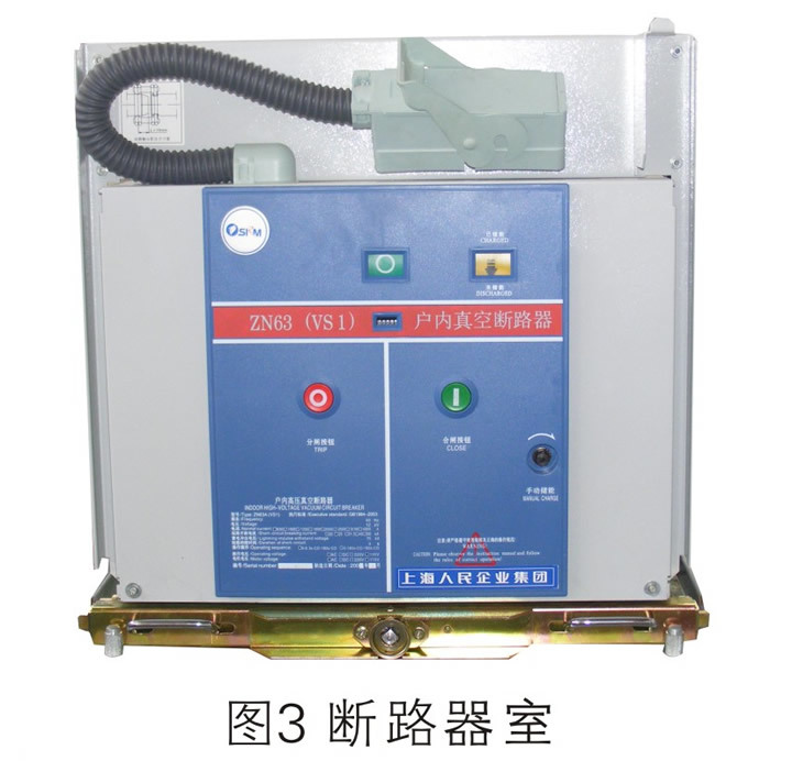
The handcart can be operated when the door panel of the switch cabinet is closed. Through the observation window, you can see the position of the handcart in the cabinet, and you can also see the O N/O FF button and the circuit breaker on the handcart of the circuit breaker. Mechanical position indicator, and spring charge/discharge status indicator.
The connection between the secondary line on the switch cabinet and the secondary line of the handcart is realized through the manual secondary plug. The moving contact of the secondary plug is connected to the handcart through a nylon bellows. The secondary socket is installed on the upper right of the circuit breaker room of the switch cabinet. Only when the handcart is in the "test/isolation" position, it can Plug and unplug the secondary plug. When the handcart is in the "working" position, due to the mechanical interlock, the secondary plug is locked and cannot be removed. The handcart of the circuit breaker can only be opened manually before the secondary plug is connected, but because the closing locking electromagnet of the handcart of the circuit breaker is not energized, it cannot be closed manually. handcart
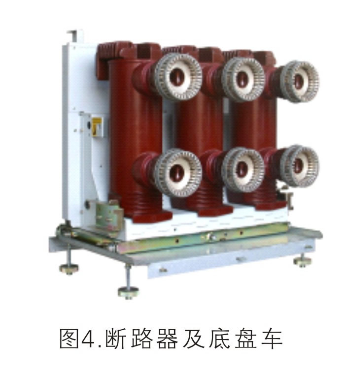
The handcart frame is made of cold-rolled steel plate after bending and welding. According to the purpose, the handcarts configured in the circuit breaker room can be divided into V D 4, V S 1, 3 A H vacuum circuit breaker handcarts, V C fuse-vacuum contactor handcarts, current transformer handcarts, voltage transformer handcarts, Isolate the handcart, etc. The height and depth of all kinds of handcarts are uniform, and handcarts of the same specification can be interchanged.
According to the need, a potential transformer handcart can also be configured in the cable room.
The circuit breaker handcart has a "working" position and a "test/isolation" position in the cabinet. Each position is equipped with a positioning locking device to ensure that the handcart is only allowed to operate when it is in a specific position.
The moving handcart must meet the interlocking conditions to ensure that the circuit breaker must be separated before the handcart moves.
When the circuit breaker handcart is pushed into the switch cabinet from the service trolley, it is first in the "test/isolation" position, and then the handcart is moved into the "working" position by shaking the handle or the electric operating mechanism.
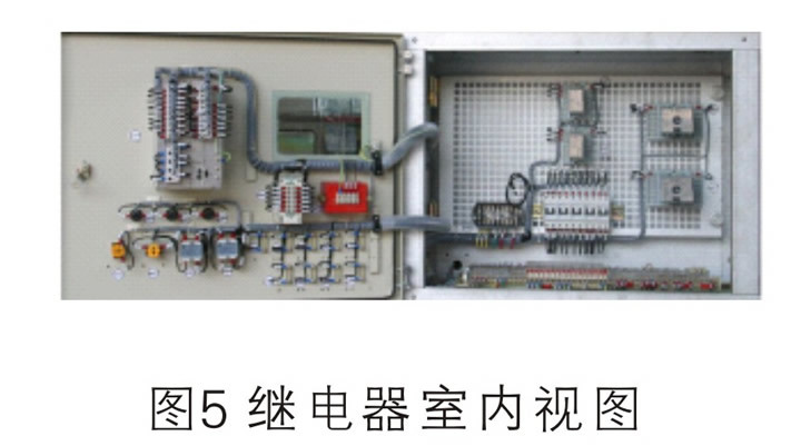
Low Pressure Chamber
The panel and interior of the low-voltage room (Figure 5) can be equipped with relay protection components, instruments, live monitors, analog busbars, operation switches and secondary equipment with special requirements.
Standard grid panels are used to install secondary equipment indoors, which can flexibly arrange various secondary components and facilitate wiring.
The control cables and secondary lines are laid in the trunking with sufficient space on both sides, and there is a metal cover. The left wire slot is reserved for the control cables connected to the outside of the cabinet, and the secondary wire inside the switch cabinet is laid in the right wire slot. There are also small busbar passing holes on the side plate of the low-voltage room, which is convenient for on-site installation.
Prevent misoperation and interlock device
Mechanical locking function
The switchgear has a reliable interlocking device to ensure the personal safety of the operator and the safety of the equipment, which meets the requirements of SD 3 1 8 "Technical Conditions for Locking Devices of High-Voltage Switchgear". When the grounding switch and circuit breaker are in the opening position, the handcart can only move from the "test/isolation" position to the "working" position; and when the grounding switch is in the closing position, the handcart cannot move from the "test/isolation" position to the "working" position; Moved from "Quarantine" to "Work":
The earthing switch can only be operated when the handcart is in the "test/isolate" or removed position:
Only when the circuit breaker trolley is correctly in the "test/isolation" position or "work" position can the closing operation be performed:
Main Circuit Scheme
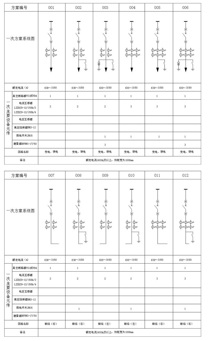
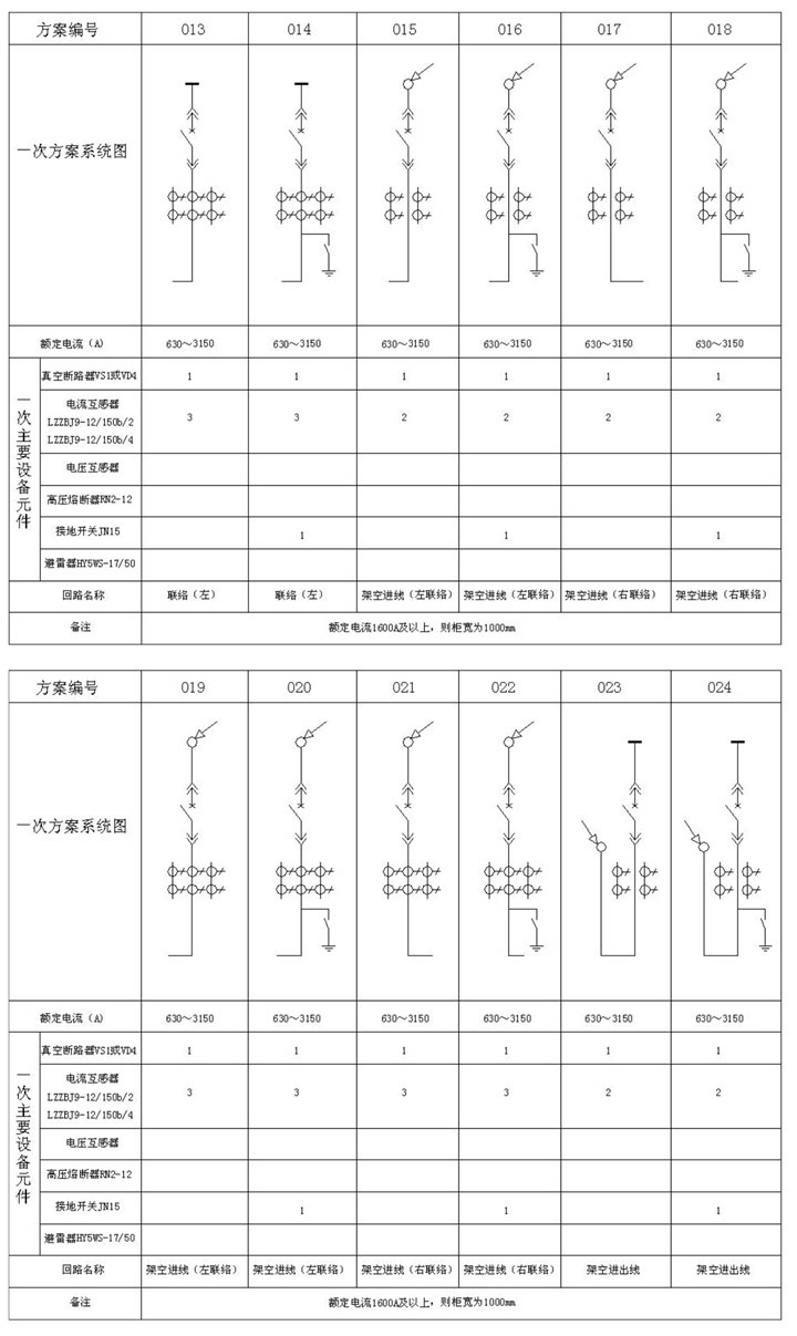
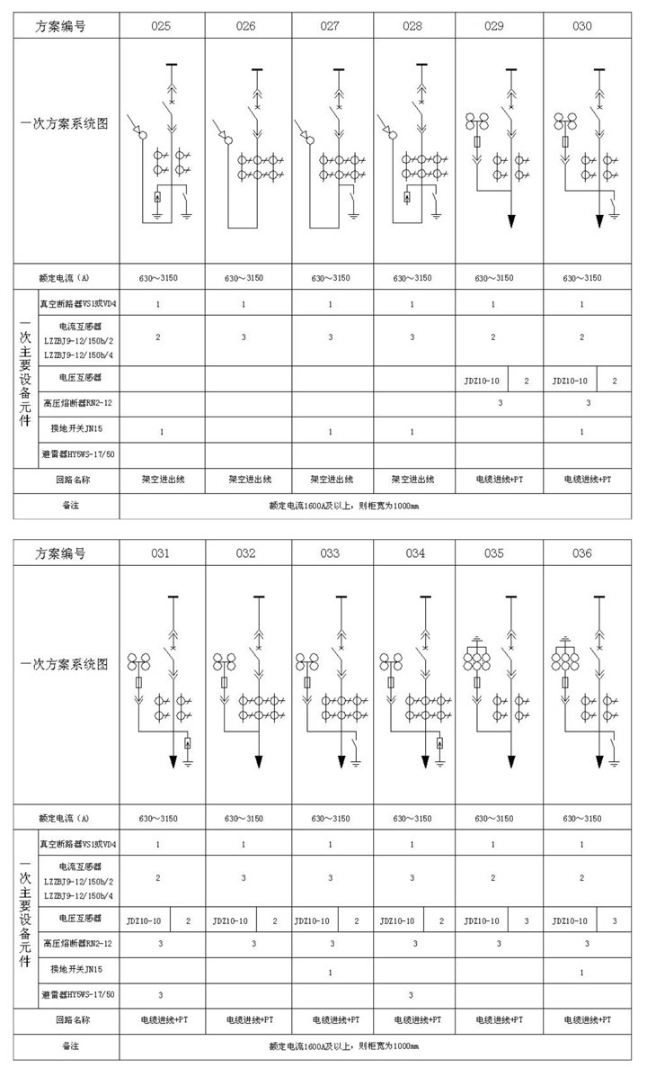
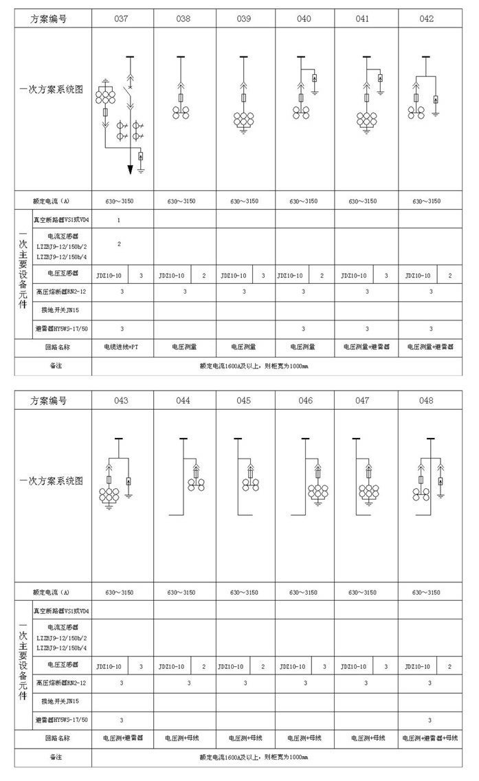
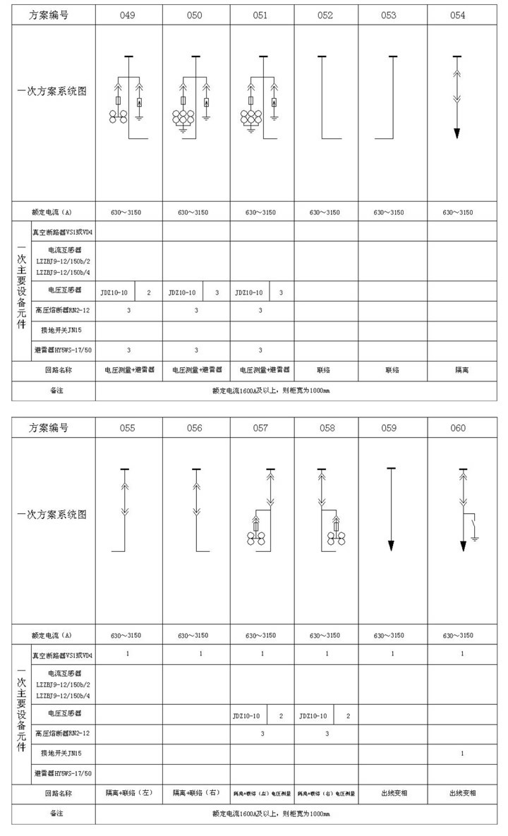
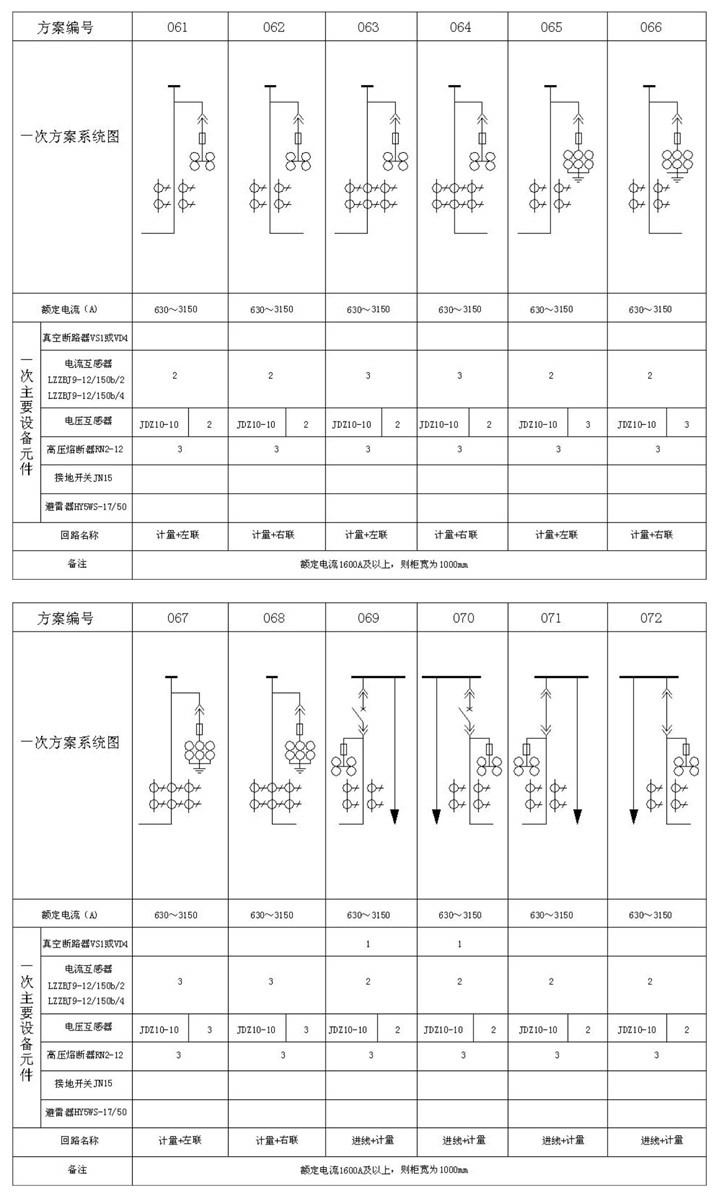

Solution application examples
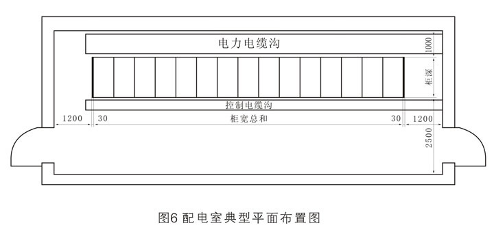
Switch cabinet layout
Since the installation, commissioning and operation of the switchgear are carried out at the front, the switchgear can be installed against the wall to save floor space. However, if conditions permit, it is still recommended to leave appropriate longitudinal passages between the rear cover of the switchgear and the wall, and between both sides of the switchgear and the wall. Figure 6 shows the reference scheme for the plane layout of the power distribution room. This layout scheme can be referred to regardless of whether the power distribution room is introduced into the cable trench, installed under the cable layer, or installed above the cable. Figure 6 shows the arrangement of switch cabinets in a single row. If the switches are arranged in double rows face to face, the distance between the two rows of switch cabinets shall not be less than 2300mm.
Embedding of switchgear foundation
The construction of the switchgear foundation should comply with the relevant provisions of the technical specifications for construction and acceptance of electric power construction.
Regardless of the way of entering and exiting the wires, it is recommended to use a pre-processed frame base as the foundation of the switchgear.
As shown in Figure 7, the foundation frame of the switchgear generally requires the method of secondary watering. After the civil construction is completed, the electrical installation unit will bury it. The foundation frame should be drawn according to the requirements of the design department and the manufacturer. Drawings are made.
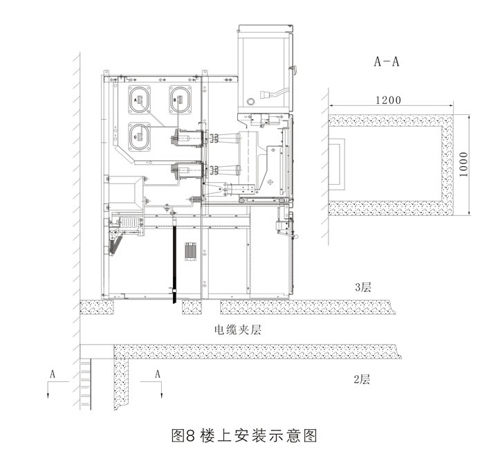
If there is a power distribution room on the upper floor, refer to Figure 8 for installation.
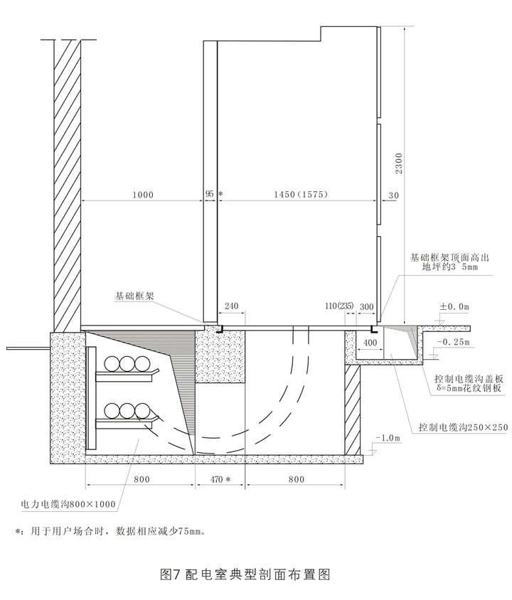
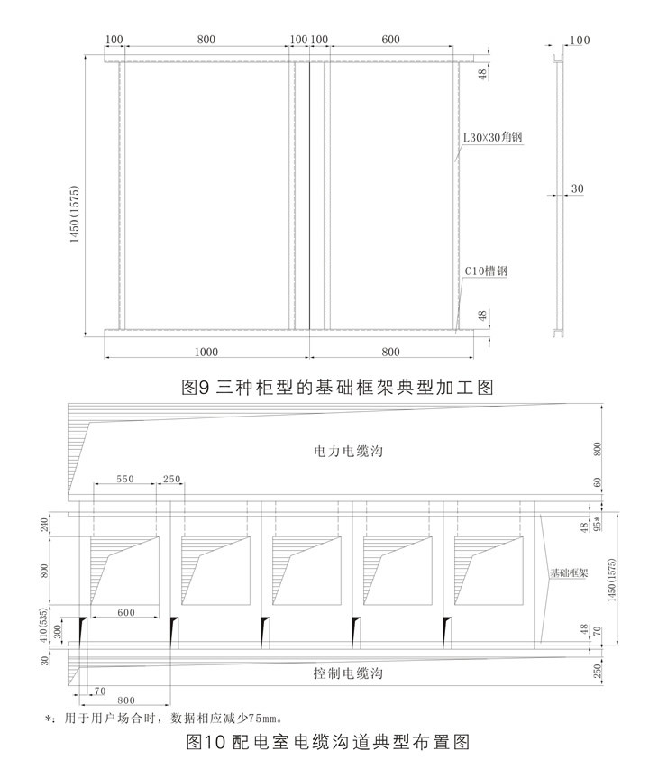
The foundation elevation of the timing switchgear for civil construction should consider the reserved height of the channel steel of the foundation frame, with a slight margin, as shown in Figure 9, and pre-buried and anchored at intervals of 1 to 1.5m along the longitudinal direction of the frame on the basis of the switchgear steel plate. Figure 9 is a schematic diagram of the processing dimensions of the basic frames of three different cabinet widths of 1000, 800, and 650mm.
The basic frame is composed of welded channel steel and angle steel. The basic size requirements of the frame and the cable channel layout are shown in Figure 10. There is no strict requirement on the height of the channel steel. C5 or C8 channel steel can be used. The extension distance of the channel steel of the foundation frame should be consistent with the size of the switchgear body frame, and its value is 1175 (1375) mm. The total length of the frame is determined according to the layout of the switchgear and the number of switchgears in each row.
When the foundation frame is pre-embedded, horizontal calibration should be carried out. The horizontal error and straightness should not exceed 1mm per meter, and the total error should not exceed 2mm. The top surface of the foundation frame should be higher than the final floor of the power distribution room by about 3 to 5mm. The foundation is preferably terrazzo. If it is a cement floor, the cement grade should not be lower than 500#.
The depth of the cable trench should be determined according to the type of cable and the requirements of the regulations.
Switchgear Installation
Armored metal-enclosed switchgear should be installed in a dry, clean, and air-circulating power distribution room. During installation, it is required that the basic frame of the switchgear in the power distribution room and the indoor floor have been completed and accepted, and the door and window decoration and indoor lighting and ventilation projects in the power distribution room should be basically completed.
After using the hook or stick to move the switchgear to the foundation and place it in place, screw down the foot adjustment screw to make it support the entire switchgear, then pull out the stick to reset the foot adjustment screw and adjust each Check the verticality of the cabinets, arrange them neatly according to the arrangement diagram and screw on the cabinet screws to fix the whole arrangement.
Order Notes
1. Provide the main wiring scheme number, purpose and single-line system diagram, rated voltage, rated current, rated short-circuit breaking current, layout diagram of power distribution room and layout diagram of switchgear, etc.
2. Indicate the specifications of the incoming/outgoing cables;
3. Requirements for switchgear control, measurement and protection functions, and requirements for other locking and automatic devices.
4. The type, specification and quantity of the main electrical components in the switchgear:
5. If busbar bridge connection is required between switch cabinets or incoming cabinets, specific requirements such as the rated carrying capacity of the busbar bridge, the span of the busbar bridge, and the height from the ground shall be provided;
6. When the switchgear is used in special environmental conditions, it should be specified when ordering:
7. When other or exceeding accessories and spare parts are needed, the type and quantity should be mentioned.
Keywords: high voltage | low ark | box complete sets of equipment
Recommended product


 low pressure enclosed power cabinet")
Online message
E-mail:sales@hfliyuan.com
Tel:86-0551-62578999
Add: Liyuan High-tech Industrial Park, intersection of Tangkou Road and Bagongshan Road, Taohua Industrial Park, Jingkai District, Hefei City

Follow us